
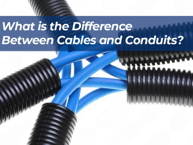
1. Introduction When working on an electrical project, it’s common to see cables and conduits purchased together. In fact, many...
Read More
How to Bend Electrical Conduit Without a Bender
1. Introduction “Can I bend electrical conduit without a special tool?” That’s a common question from people working on electrical...
Read More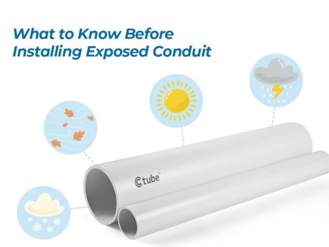
What to Know Before Installing Exposed Conduit
1. Introduction When we think about electrical conduit, we often imagine it hidden behind walls or ceilings. But in many...
Read More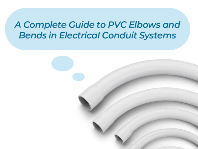
A Complete Guide to PVC Elbows and Bends in Electrical Conduit Systems
1. Introduction In any electrical conduit system, straight runs of pipe are just the beginning. To navigate corners, avoid structural...
Read More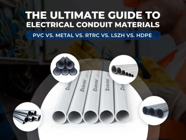
PVC vs. Metal vs. RTRC vs. LSZH vs. HDPE, The Ultimate Guide to Electrical Conduit Materials (2025)
1. Introduction An electrical conduit pipe is a protective tubing system designed to house and safeguard electrical wiring from mechanical...
Read More
Ultimate Guide to Cable Trunking: Design Types, Sizes, Regulations, and Best Practices
1. Introduction to Cable Trunking Systems Cable trunking is an essential component of electrical installations, designed to house and protect...
Read More
IEC 61386 Standard PVC Conduit – Everything You Need to Know
1. Introduction When it comes to electrical installations, selecting the right conduit is crucial for ensuring safety, durability, and performance....
Read More
Top 10 PPR Pipe Manufacturers and Suppliers in China
1. 联塑 (LESSO Group) Introduction: Established in 1986 and listed on the Hong Kong Stock Exchange (HKEX: 2128), LESSO Group...
Read More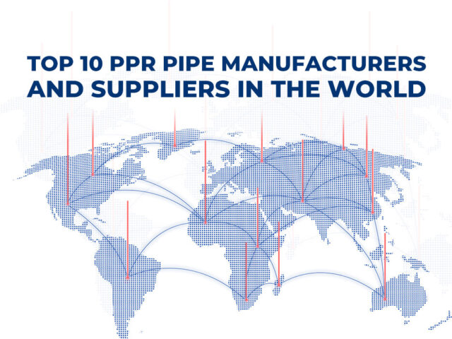
Top 10 PPR Pipe Manufacturers and Suppliers in the World
PPR (Polypropylene Random Copolymer) pipes have become a cornerstone in modern infrastructure due to their durability, resistance to corrosion, and...
Read More
Guide to Selecting the Best Conduit for Your Fiber Optic Project
1. Introduction 1.1 Overview of Fiber Optic Installations Fiber optic technology is the backbone of modern communication, enabling high-speed internet,...
Read More