
1. Einleitung
Bei Elektroinstallationen ist die Wahl des richtigen Schutzrohrs entscheidend für Sicherheit, Langlebigkeit und Leistungsfähigkeit. Unter den verschiedenen verfügbaren Schutzrohrmaterialien zeichnet sich PVC (Polyvinylchlorid) aufgrund seiner Flexibilität, Korrosionsbeständigkeit und einfachen Installation als beliebte Wahl aus. Die Norm IEC 61386 liefert wichtige Richtlinien für die Klassifizierung und die Leistungsanforderungen von Schutzrohrsystemen und gewährleistet so die Einhaltung globaler Sicherheits- und Zuverlässigkeitsstandards.
Ob Wohn-, Gewerbe- oder Industrieprojekt: Das Verständnis der Spezifikationen und Vorteile von Leitungsrohren gemäß IEC 61386 ist entscheidend für fundierte Entscheidungen. Dieser Artikel beleuchtet die Details von Leitungsrohrsystemen nach IEC 61386 und vergleicht PVC-Rohre mit herkömmlichen Metallrohren. Wir hoffen, dass Sie nach der Lektüre dieses Leitfadens ein umfassendes Verständnis der Leitungsrohrklassifizierungen, Leistungstests und bewährten Verfahren zur Auswahl des richtigen Systems für Ihre Elektroprojekte besitzen.
Beginnen wir mit dem Titel des ersten Kapitels, gefolgt von einer detaillierten Erläuterung der IEC und der Norm IEC 61386.
2. IEC- und IEC 61386-Standard verstehen
2.1 Was ist die IEC?
Die Internationale Elektrotechnische Kommission (IEC) ist eine globale Normungsorganisation, die internationale Normen für alle elektrischen, elektronischen und verwandten Technologien erarbeitet und veröffentlicht. Die 1906 gegründete IEC spielt eine entscheidende Rolle für die Sicherheit, Qualität und Interoperabilität elektrischer Produkte und Systeme weltweit. Ihre Normen werden von Regierungen, Herstellern und Aufsichtsbehörden weitgehend übernommen und anerkannt und fördern die internationale Einheitlichkeit bei Design, Produktion und Leistung elektrischer Produkte.
Die IEC spielt mit ihren vielfältigen Normen eine führende Rolle bei der Entwicklung von Kriterien für Systeme wie Kabelkanäle, Installationszubehör und elektrische Kabel. Die Organisation arbeitet eng mit nationalen Normungsinstitutionen zusammen, um die weltweite Umsetzung der IEC-Normen zu gewährleisten und so ein hohes Maß an Betriebssicherheit und technischer Kompatibilität in der Industrie zu erreichen.
2.2 Was ist die Norm IEC 61386?
Unter den wichtigsten Normen gilt IEC 61386 weithin als die maßgebliche Referenz für Rohrsysteme, die sich speziell auf die Klassifizierung und die Leistungsanforderungen von Rohrsystemen konzentriert, die zum Schutz und zur Verlegung elektrischer Leitungen verwendet werden.
2.2.1 Länder und Märkte, die IEC 61386 anwenden
China
China hat die Norm IEC 61386 in die nationale Norm GB/T 20041.1-2015 übersetzt, die für Leitungsrohrsysteme auf dem heimischen Markt gilt. Diese Anpassung gewährleistet, dass lokale Hersteller und Fachleute international anerkannte Sicherheits- und Leistungsstandards für Leitungsrohrsysteme einhalten und gleichzeitig den Anforderungen des globalen Marktes entsprechen.
Europäische Union (EU)
In der Europäischen Union wenden Länder wie Deutschland, Frankreich und andere die Norm IEC 61386 durch die CE-Kennzeichnung weitgehend an. Dies gewährleistet, dass Leitungssysteme die grundlegenden europäischen Sicherheits- und Leistungsstandards erfüllen und erleichtert den freien Warenverkehr innerhalb der EU. Die Anerkennung der IEC 61386 in der EU hilft Herstellern und Lieferanten sicherzustellen, dass ihre Leitungssysteme die strengen Marktanforderungen erfüllen.
Andere IEC-Mitgliedsländer
Australien, Japan und diverse andere IEC-Mitgliedstaaten nutzen IEC 61386 häufig als Grundlage für ihre nationalen technischen Vorschriften oder Branchenspezifikationen. Diese Länder passen die IEC-Norm zwar mitunter an lokale Gegebenheiten an, die Kernprinzipien der IEC 61386 bleiben jedoch Basis ihrer technischen Anforderungen. Die weite Verbreitung von IEC 61386 trägt zur Standardisierung von Leitungssystemen bei und gewährleistet Sicherheit, Qualität und Kompatibilität über Ländergrenzen hinweg.
2.2.2 Welche Leitungstypen werden in der Norm IEC 61386 erwähnt?
Metallische Leitungen – Bekannt für ihre hohe mechanische Festigkeit und Erdungseigenschaften.
Nichtmetallische Leitungen – Hergestellt aus Materialien wie PVC, die Korrosionsbeständigkeit und elektrische Isolierung bieten.
Verbundleitungen – Kombination der Eigenschaften metallischer und nichtmetallischer Werkstoffe für spezielle Anwendungen.
Die Norm beschreibt die Leistungsanforderungen unter normalen und extremen Bedingungen, einschließlich der Einwirkung von mechanischem Druck, thermischer Belastung und Chemikalien. Sie definiert außerdem die Prüfmethoden zur Bewertung der Einhaltung dieser Leistungskriterien.
Darüber hinaus erkennt die IEC 61386 an, dass bestimmte Leitungssysteme für den Einsatz in explosionsgefährdeten Bereichen geeignet sein können. In solchen Fällen müssen zusätzliche Anforderungen erfüllt werden, um Sicherheit und Konformität zu gewährleisten.
2.2.3 Klassifizierung von Leitungen gemäß IEC 61386
Die IEC 61386 ist in mehrere Teile gegliedert, die jeweils spezifische Arten von Leitungssystemen und deren besondere Anforderungen behandeln:
IEC 61386-21 – Starre Leitungssysteme: Definiert die Anforderungen an Leitungen, die unter mechanischer Belastung ihre feste Form beibehalten.
IEC 61386-22 – Biegsame Leitungssysteme: Umfasst Leitungen, die gebogen oder gelenkig bewegt werden können, ohne in ihre ursprüngliche Form zurückzukehren.
IEC 61386-23 – Flexible Leitungssysteme: Spezifiziert die Eigenschaften von Leitungen, die sich wiederholt biegen und biegen lassen, ohne Schaden zu nehmen.
IEC 61386-24 – Unterirdisch verlegte Leitungssysteme: Beschreibt die besonderen Anforderungen an Leitungen, die dem Erddruck, der Feuchtigkeit und Temperaturschwankungen ausgesetzt sind.
IEC 61386-25 – Befestigungselemente für Leitungsrohre: Definiert die Leistungsanforderungen an Komponenten, die zur Befestigung von Leitungsrohrsystemen verwendet werden.
Dieses Klassifizierungssystem ermöglicht es Herstellern, Installateuren und Prüfern, das geeignete Leitungssystem für spezifische Anwendungen auszuwählen und so Konsistenz und die Einhaltung internationaler Sicherheits- und Leistungsstandards zu gewährleisten.
Hier stellen wir Ihnen einige Details zur IEC und zum IEC 61386-Standard vor.
Im folgenden Abschnitt werden wir uns genauer mit IEC 61386-1 befassen, einem wichtigen Bestandteil der Normenreihe IEC 61386, in der die allgemeinen Anforderungen an Leitungssysteme festgelegt sind.
3. Einführung der wichtigsten Anforderungen der Norm IEC 61386
Die Norm IEC 61386-1 enthält detaillierte Richtlinien und Leistungskriterien für Schutzrohre und Formstücke zum Schutz und zur Führung isolierter Leiter und Kabel in elektrischen Anlagen oder Kommunikationssystemen. Diese Systeme sind für den Einsatz in Umgebungen mit elektrischen Spannungen bis zu 1000 V AC und 1500 V DC ausgelegt und eignen sich daher sowohl für Wohngebäude als auch für industrielle Anwendungen.
3.1 Allgemeine Anforderungen und Testbedingungen
Hier geben wir eine Zusammenfassung der allgemeinen Anforderungen an Leitungssysteme und der Bedingungen, unter denen sie geprüft werden.
3.1.1 Allgemeine Anforderungen
Planung und KonstruktionLeitungen und Leitungsformstücke müssen so konstruiert und gefertigt sein, dass sie im Normalbetrieb zuverlässig funktionieren. Sie müssen sowohl den Benutzer als auch die Umgebung ausreichend schützen.
Montage und SchutzBei sachgemäßer Montage gemäß den Anweisungen des Herstellers müssen Leitungen und Formstücke einen mechanischen Schutz und gegebenenfalls einen elektrischen Schutz für die darin befindlichen Kabel und Leiter gewährleisten.
GelenkintegritätDie Schutzeigenschaften der Verbindung zwischen dem Schutzrohr und dem Formstück müssen die für das gesamte Schutzrohrsystem festgelegten Schutzniveaus erreichen oder übertreffen.
HaltbarkeitLeitungen und Formstücke müssen den Belastungen während Transport, Lagerung, Installation und regelmäßiger Anwendung standhalten, ohne dass ihre Leistungsfähigkeit beeinträchtigt wird.
EinhaltungDie Einhaltung dieser Anforderungen wird durch die Durchführung der in der Norm beschriebenen Tests überprüft.
3.1.2 Allgemeine Bedingungen für Prüfungen
TyptestsAlle gemäß der Norm durchgeführten Prüfungen sind Typprüfungen. Leitungssysteme mit derselben Klassifizierung (auch wenn die Farben variieren) müssen für Prüfzwecke als derselbe Produkttyp betrachtet werden.
UmgebungstemperaturSofern nicht anders angegeben, sollten die Tests bei einer Umgebungstemperatur von 20 ± 5°C durchgeführt werden.
ProbenbedingungenDie Prüfungen werden in der Regel an drei neuen Proben durchgeführt, die aus einem Rohrabschnitt entnommen werden. Nichtmetallische oder Verbundrohre und Formstücke sollten vor der Prüfung mindestens 240 Stunden lang bei 23 ± 2 °C und 40–601 % relativer Luftfeuchtigkeit konditioniert werden.
Zustand der ProbenDie Muster müssen sauber sein und alle Teile müssen so montiert sein, wie sie im normalen Gebrauch verwendet würden. Leitungssysteme sollten gemäß den Anweisungen des Herstellers montiert werden, insbesondere wenn zum Verbinden von Verbindungen Kraftaufwand erforderlich ist.
Testfehler und MaßnahmenWenn eine Probe die Testanforderungen nicht erfüllt, werden die verbleibenden Tests gegebenenfalls an weiteren Proben durchgeführt. Ein negatives Testergebnis erfordert eine vollständige Wiederholungsprüfung aller Proben, um die Einhaltung der Anforderungen sicherzustellen.
3.2 Klassifizierungskriterien gemäß IEC 61386
Die Norm IEC 61386 klassifiziert Leitungssysteme anhand ihrer mechanischen, elektrischen, thermischen, witterungsbeständigen und flammwidrigen Eigenschaften. Sie beinhaltet keine praktischen Prüfungen, sondern legt fest, wie Leitungen nach spezifischen Eigenschaften klassifiziert werden. Die Klassifizierung hilft Anwendern, den passenden Leitungstyp für ihre Anwendung auszuwählen. Im Folgenden finden Sie einige Details zum besseren Verständnis.
3.2.1 Mechanische Eigenschaften
Leitungssysteme werden nach ihrer Fähigkeit, unterschiedlichen mechanischen Belastungen standzuhalten, klassifiziert.
Widerstand gegen KompressionDie Bandbreite reicht von sehr leicht über leicht, mittel und schwer bis hin zu sehr schwer.
Widerstandsfähigkeit gegen Stöße: Kategorisiert von Sehr leicht bis Sehr schwer, was angibt, wie gut das Rohr physische Stöße oder Erschütterungen verkraftet.
Widerstand gegen BiegungDie Klassifizierungen umfassen starr, biegsam, selbstheilend und flexibel und zeigen an, wie leicht sich das Rohr biegen lässt oder in seine ursprüngliche Form zurückkehrt.
Zugfestigkeit: Reicht von sehr leicht bis sehr schwer und definiert die Fähigkeit des Materials, einer Dehnung unter Spannung zu widerstehen.
Tragfähigkeit für hängende LastenDie Klassifizierungen von Sehr Leicht bis Sehr Schwer geben an, wie viel Gewicht das Rohr im aufgehängten Zustand tragen kann.
3.2.2 Temperaturbereiche
Leitungssysteme werden anhand ihrer Beständigkeit gegenüber extremen Temperaturen klassifiziert:
Unterer TemperaturbereichKlassifizierungen von +5°C bis -45°C, die die Mindesttemperatur definieren, bei der das Rohr transportiert, installiert und verwendet werden kann.

Oberer TemperaturbereichDie Klassifizierungen reichen von 60°C bis 400°C und geben die maximale Temperatur an, der das Rohr während der Anwendung und Installation standhalten kann.

3.2.3 Elektrische Eigenschaften
Leitungssysteme müssen bestimmte elektrische Anforderungen erfüllen:
Mit elektrischen DurchgangseigenschaftenDiese Klassifizierung gewährleistet, dass die Leitung die elektrische Kontinuität aufrechterhält und somit Erdung und Schutz bietet.
Mit elektrischen Isolationseigenschaften: Zeigt die Fähigkeit des Rohres an, als Isolator zu wirken und den Durchfluss von elektrischem Strom zu verhindern.
3.2.4 Widerstandsfähigkeit gegenüber äußeren Einflüssen
Die Fähigkeit der Leitung, äußeren Umwelteinflüssen standzuhalten, wird wie folgt kategorisiert:
Schutz gegen das Eindringen fester GegenständeDer Schutzgrad ist nach IEC 60529 definiert und beträgt mindestens IP3X.
Schutz gegen das Eindringen von WasserDie Klassifizierung basiert auf der Fähigkeit, das Eindringen von Wasser in die Leitung zu verhindern, wobei eine Mindestschutzart von IPX0 erforderlich ist.
Beständigkeit gegen KorrosionLeitungen können je nach Material und Verwendungszweck mit oder ohne Korrosionsschutz klassifiziert werden.
3.2.5 Flammenausbreitung
Leitungssysteme werden nach ihrer Beständigkeit gegen Flammenausbreitung klassifiziert:
Nichtflammenausbreitend: Ein Rohr, das die Ausbreitung von Flammen entlang seiner Länge verhindert.
Flammenausbreitung: Ein Leitungsrohr, das die Ausbreitung von Flammen ermöglichen kann, obwohl es in der Regel bis zu einem gewissen Grad feuerbeständig ist.
Darüber hinaus können Leitungen in Ländern wie Australien und Österreich nach dem Kriterium niedriger Säuregasemissionen klassifiziert werden, was ihre Fähigkeit zur Beständigkeit gegenüber bestimmten Umweltgefahren anzeigt.
3.3 Kennzeichnungs- und Dokumentationsanforderungen
Hier fassen wir auch die Kennzeichnungsanforderungen gemäß IEC 61386 zusammen. Das Verständnis der Kennzeichnungs- und Dokumentationsanforderungen für Leitungssysteme ist sowohl für Lieferanten als auch für Kunden unerlässlich.
Für Lieferanten, Es gewährleistet die Einhaltung internationaler Standards, verbessert die Rückverfolgbarkeit und stärkt den Markenruf durch klare Produktidentifizierung und zuverlässige Informationen.
Für Kunden, Dadurch wird sichergestellt, dass sie qualitativ hochwertige Produkte erhalten, die spezifische Leistungskriterien erfüllen, die richtige Produktauswahl erleichtert wird und eine einfache Installation sowie unkomplizierter Support gewährleistet sind. Eine korrekte Kennzeichnung ermöglicht eine reibungslose Abwicklung und stärkt das Vertrauen in die Sicherheit und Zuverlässigkeit der Produkte.
HerstellerkennzeichnungJede Leitung muss mit dem Namen oder der Marke des Herstellers bzw. des verantwortlichen Lieferanten und einer Produktkennzeichnung (z. B. Katalognummer oder Symbol) zur einfachen Identifizierung versehen sein.
KlassifizierungscodeDie Schutzleitung oder ihre kleinste gelieferte Einheit muss mit einem Klassifizierungscode gekennzeichnet sein. Dieser Code muss gemäß Anhang A mindestens die ersten vier Ziffern enthalten und deutlich lesbar sein.
Selbstheilende LeitungenSelbstheilende Schutzrohre müssen außerdem den Klassifizierungscode auf dem Schutzrohr oder der kleinsten mitgelieferten Verpackung tragen, wobei ein deutliches Etikett mindestens die ersten fünf Ziffern ausweisen muss.
Compatibility and Classification: The manufacturer is responsible for indicating the compatibility of parts within a conduit system and must provide full classification in the product’s literature, along with necessary information for proper transport, storage, installation, and use.
Flame Propagation: Conduits made of flame-propagating materials must be marked with a specific symbol (flame icon) along their entire length, ideally at intervals no longer than 1 meter. If the package prevents the mark from being seen, it should be labeled on the packaging instead.
Earthing Facilities: Conduits with earthing facilities must be marked with the IEC 60417-5019 symbol for protective earth, but this should not be placed on removable parts like fittings.
Durability and Legibility: Markings must be durable, clear, and legible, checked through normal or corrected vision. The marking surface should also undergo rubbing tests to ensure durability, with specific procedures for testing marking endurance under various conditions.
Inspection Compliance: All markings must be inspected to ensure they comply with the outlined standards. This includes visual checks and rubbing tests with cotton soaked in solvents like n-hexane 95%, ensuring they remain intact under normal handling and wear.
3.4 Abmessungen und Konstruktionsanforderungen für Leitungssysteme
Understanding the dimensions and construction requirements of conduit systems is crucial for ensuring safe installation and reliable performance.
3.4.1 Dimensions Compliance
Thread and External Diameters: Conduit threads and external diameters must comply with IEC 60423 standards. This ensures that all thread sizes and diameters are uniform and meet the necessary specifications for compatibility and safety.
Other Dimensions: For all other dimensions, conduit systems should meet the requirements outlined in Part 2 of IEC 61386, ensuring consistency and standardized measurements across different types of conduit systems.
3.4.2 Construction Standards
Sharp Edges and Burrs: Conduit systems must be designed and constructed without sharp edges, burrs, or surface projections that could damage cables or harm installers and users during handling and installation.
Screws: Screws used to attach components or covers must comply with specific guidelines:
- ISO Metric Threads: All screws must use ISO metric threads to prevent damage to cable insulation during installation.
- Thread-Cutting Screws: Thread-cutting screws should not be used to avoid damaging the conduit or fittings.
Screw Fixing and Torque: Screws for securing conduit parts must be able to withstand mechanical stresses during installation and normal use. For fixing with preformed thread screws, the screws should be tightened and loosened 10 times (or 5 times for specific cases) without sustaining damage. Thread-forming screws should be tested for torque values as specified in Table 3, ensuring proper installation and durability without damaging the screw or the threaded part.

Material and Resistance: Any material inside the joint (e.g., rubber, fiber) exposed to external influences must provide the same level of protection as the conduit or fitting itself. This ensures the system’s overall resistance to environmental factors.
Disassembly: For conduit systems assembled without threads, manufacturers should specify whether the system can be disassembled and how this can be done safely, ensuring ease of maintenance and flexibility.
4. Detaillierte Prüfungen von Leitungsrohren gemäß IEC 61386
4.1 Mechanische Eigenschaften gemäß IEC 61386
Conduit systems must exhibit adequate mechanical strength to handle the forces they are subjected to during use. These systems, depending on their classification, should not crack or deform to the extent that insulated conductors or cables become difficult to insert. They must also be capable of supporting equipment if used as mounts, both during installation and operation. They should be verified through tests in the following. So in the following, we will make detailed introduction about this tests.
For better understanding, unless otherwise specified, the relevant tests mentioned below are typically required for all types of electrical conduits, including metallic, non-metallic, and composite conduits.
4.1.1 Compression Test
Samples of conduit (200 ± 5 mm long) are tested for compression by applying a gradually increasing force, reaching the value specified for each conduit classification. After the force has been applied, the sample’s outer diameter is measured again to check for any deformation. The difference between the initial and flattened diameter should not exceed 25% of the original dimension. The force is then removed, and the sample is checked for cracks. This test ensures the conduit can withstand compression during installation and use.

4.1.2 Impact Test
This test evaluates the impact resistance of conduit systems by subjecting twelve samples (200 ± 5 mm long) to a specified impact. The samples are first conditioned at the required temperature, and then a hammer is dropped onto the sample to simulate potential real-world impacts. The mass of the hammer and fall height vary depending on the conduit classification, with heavier classes requiring more significant impact tests. After the test, the conduit must show no significant damage, cracks, or deformation.

4.1.3 Bending Test
The Bending Test is conducted to ensure that both metallic and non-metallic conduits can withstand bending during installation without damage.
For metallic conduits (sizes 16, 20, and 25), the samples are bent to an angle of 90° ± 5° with an inside radius up to six times the nominal diameter. After bending, the conduit should show no cracks, openings, or excessive distortion, and the seams must remain intact. For conduits with welded seams, both sides of the bend are tested to ensure the conduit remains structurally sound.
For non-metallic conduits, the bending process is similar, with a length of 500 mm ± 10 mm and conducted at a temperature of 12 ± 2°C. These samples must also show no visible damage, such as cracks or distortion, after the test. The conduit should be able to return to its straight form under its own weight without requiring any initial speed.
For Composite conduits, they are declared by the manufacturer as being bendable are tested as metallic and non-metallic conduit.
4.1.4 Flexing Test
The Flexing Test is conducted to ensure that conduit systems, particularly flexible conduits, can withstand repeated movement without damage. The test is performed on six samples, with three tested at the minimum and three at the maximum declared temperatures for transport, application, and installation.
For flexible conduits, the test ensures that the product is suitable for transport and installation at both ambient and maximum temperatures as per the manufacturer’s specifications. If the conduit is only suitable for ambient temperature flexing, the test is conducted at 20 ± 2°C.
The samples are fixed to an oscillating member and subjected to a back-and-forth motion at a frequency of 5,000 flexes over a 180° angle. The test is performed at a speed of 40 ± 5 flexes per minute. After completing the flexing cycle, the samples must show no visible cracks or damage under normal or corrected vision, confirming the conduit’s durability under repeated motion.
This test ensures that flexible conduits maintain their integrity during installation and handling, making them suitable for environments requiring frequent movement or bending.
4.1.5 Collapse Test
The Collapse Test evaluates the ability of non-metallic and composite conduits to withstand external pressures without deforming or collapsing. Metallic conduits are not subject to this test.
For non-metallic conduits, which are classified as bendable by the manufacturer, the samples are bent and then fixed to a rigid support using four straps, as outlined in the manufacturer’s instructions. The samples are then placed in a heating cabinet at a specified temperature for 24 ± 15 minutes to condition them properly. After this period, the conduit is positioned so that the straight portions of the sample are at a 45° angle to the vertical, ensuring they maintain their integrity when subjected to external forces.
The test ensures that the conduit can withstand pressure without collapsing or distorting, maintaining its ability to protect the cables inside. This test is essential for non-metallic and composite materials to guarantee their durability under normal use conditions.
4.1.6 Tensile Test
The Tensile Test is conducted to measure the tensile strength of conduit systems. A sample consisting of a conduit and two fittings (or terminating conduit fittings) is assembled according to the manufacturer’s instructions, ensuring that the conduit length between fittings is at least 200 mm. When this length is not feasible, the test is conducted on two samples of conduit and fittings.
The test applies a uniformly increasing tensile force until it reaches the specified value in Table 6. The force is maintained for 2 minutes ± 10 seconds at 23 ± 2°C. After the test, the conduit and fittings must remain properly assembled, with no visible damage to the components when observed without magnification.

If the tensile strength of the system is not declared, the manufacturer must ensure that the system meets
the relevant standards for tensile strength according to the appropriate part of the IEC 61386 standard. The test ensures that the system will maintain its structural integrity during use without damaging the fittings or conduit under tensile force.
4.1.7 Suspended load test
The Suspended Load Test evaluates the strength and durability of conduit fittings designed to support suspended loads. The fitting is secured to a rigid structure using a manufacturer-approved method, with the suspension means pointing downward. A specified load, based on the classification in Table 7, is applied for a duration of 48 hours.
To pass the test, the fitting must show no visible cracks or deformation that would impair its normal use. For non-metallic and composite conduit fittings, the test is conducted in a heating cabinet at the declared maximum operating temperature, with a tolerance of ±2°C.

4.2 Elektrische Eigenschaften
4.2.1 Electrical Requirements
Continuity Testing (Metallic, Composite): Conduit systems declaring electrical continuity characteristics must be tested immediately after installation.
Bonding of Metallic Parts (Metallic, Composite): Metallic or composite conduits should be constructed to allow bonding of accessible metal parts. Compliance is checked by inspection.
Earthing (Metallic, Composite): Conductive parts of metallic or composite conduits that may become live in a fault must be properly earthed. Compliance is tested via bonding.
Insulation Strength (Non-metallic, Composite): Non-metallic and composite conduit systems must have adequate insulation resistance and electrical insulating strength. Compliance is tested through dielectric strength and insulation resistance tests.
4.2.2 Bonding Test (Metallic, Composite)
To assess the electrical continuity of metallic and composite conduit systems, a bonding test is performed by connecting 10 conduit pieces with fittings according to the manufacturer’s instructions. A current of 25 A at 50-60 Hz is applied through the system for 60 seconds, with the voltage drop measured to calculate resistance. The resistance must not exceed 0.1 Ω to ensure proper electrical bonding. If different types of fittings are used, the test must be repeated for each type. Additionally, any protective coatings that could interfere with conductivity should be removed before testing.
4.2.3 Dielectric Strength and Insulation Resistance (Non-metallic, Composite)
For non-metallic and composite conduit systems, insulation strength is tested by immersing samples in a saltwater solution. After soaking, a high-voltage test is conducted by gradually increasing the voltage to 2,000 V AC over 15 minutes and maintaining it for 5 seconds. The system is considered compliant if it withstands this voltage without tripping a 100 mA safety circuit. Insulation resistance is also measured after voltage application, and the system must exhibit a resistance of at least 100 MΩ to pass.
Conduit fittings undergo similar testing procedures. Samples are immersed in water for 24 hours, then dried before testing. The fittings are sealed with insulating material, and an electrode is inserted to simulate real installation conditions. After a high-voltage test, the insulation resistance must be greater than 5 MΩ to be considered compliant.
4.3 Thermische Eigenschaften
Non-metallic and composite conduits must demonstrate sufficient heat resistance. Compliance is determined through standardized testing procedures. Metallic conduits are not explicitly mentioned in this section, as metal typically has different thermal performance criteria.
The heating test follows the classification of the conduit’s declared compression rating. Samples of conduit (each 100 ± 5 mm) are heated for 4 hours and 5 minutes at the specified temperature (see Table 8) with a ±2°C tolerance.
After heating, a load is applied for 24 hours and 15 minutes using a 6.0 ± 0.1 mm steel rod, positioned perpendicularly to the conduit’s axis. The total applied load corresponds to the classification in Table 8, ensuring accurate mechanical stress simulation.
Once the load is removed, the conduit must allow an appropriately sized gauge to pass through under its own weight without external force. This test ensures the conduit retains its internal dimensions and structural integrity after thermal and mechanical stress.
4.4 Brandgefahr
Non-metallic and composite conduits are subject to all fire hazard tests, including glow wire and flame application assessments, to ensure they meet fire resistance standards. Metal conduits are not explicitly mentioned in the testing criteria.
4.4.1 Reaction to Fire
Conduit systems are not in direct contact with live parts, meaning they do not pose an immediate risk of fire initiation. However, their contribution to fire and flame spread must be evaluated, particularly for non-metallic and composite conduit fittings.
4.4.2 Contribution to Fire
Non-flame propagating conduit systems must have adequate resistance to flame spread. Compliance for non-metallic and composite conduit fittings is assessed through two main tests. The first is the Glow Wire Test, conducted per IEC 60695-2-11, where a heated wire at 750°C is applied to the conduit in a vertical position. The conduit passes if it does not exhibit visible flames or sustained glowing, or if any flames extinguish within 30 seconds after wire removal.
The second test applies a 1 kW flame, in accordance with IEC 60695-11-2. The conduit sample is placed vertically inside a metal enclosure with an open face to minimize external air interference. This test further evaluates the flame resistance of non-metallic and composite conduits under direct fire exposure.
4.4.3 Spread of Fire
To ensure fire resistance, conduits are tested by direct flame exposure at a 45° angle within a controlled metal enclosure. Samples are securely mounted with clamps to prevent deformation during testing. A steel rod provides additional support for thinner conduits. Flame exposure time varies based on material thickness, as outlined in Table 9, with times ranging from 20 seconds for 0.5 mm thick conduits to 500 seconds for conduits up to 8 mm thick.

A conduit passes if it does not ignite, or if it self-extinguishes within 30 seconds after flame removal. Additionally, the test ensures that a tissue paper placed below the conduit does not ignite, and there is no charring or burning extending beyond 50 mm from the flame exposure point. These criteria ensure that non-metallic conduits meet fire safety standards, preventing flame spread in electrical installations.
4.4.4 Additional Fire Reaction Characteristics
In some regions, non-metallic conduits must also meet low acid gas emission standards.
In Australia, conduits classified as low acid gas emission are tested under IEC 60754-1, where emissions must not exceed 5 mg of hydrochloride acid per gram of material.
In Austria, similar regulations apply under IEC 60754-2. These requirements help reduce toxic gas emissions in the event of a fire, improving safety in enclosed environments.
4.5 Externe Einflüsse
Enclosure protection applies to non-metallic and metallic materials, but corrosion resistance and testing focus on metallic systems, while non-metallic materials are not explicitly tested, they sometimes have an inherent resistance to chemicals.
4.5.1 Degree of Protection Provided by Enclosure
Conduit systems must provide adequate resistance to external influences based on the classification declared by the manufacturer, with a minimum requirement of IP30. Compliance is verified through specific tests assessing protection against solid objects and water ingress.
Protection Against Foreign Solid Objects: Assemblies made of conduit and fittings are tested to ensure no visible ingress of dust under normal vision. Tests follow IEC 60529 standards, and systems achieving numeral 5 or 6 are deemed compliant.

Protection Against Water Ingress: Conduit assemblies, including fittings, are tested for water resistance using IEC 60529 methods. For numerals 3 and 4, an oscillating tube test is used to assess water penetration. Systems rated numeral 1 and above pass if water ingress does not form visible droplets under normal vision.

4.5.2 Resistance to Corrosion
Both metallic and composite conduit systems, excluding screw threads, must demonstrate adequate resistance to corrosion for both interior and exterior applications. Corrosion resistance is classified into four levels:
Low Protection: Basic coatings like priming paint.
Medium Protection: Stove enamel or electro zinc plating.
Medium/High Protection: Enhanced coatings like Sherardizing.
High Protection: Heavy-duty coatings such as stainless steel or hot-dip zinc coating.
4.5.3 Corrosion Testing for Different Materials
For painted and zinc-coated steel and composite conduit systems, compliance is verified through specific tests.
Low Protection: Inspected for complete coverage.
Medium Protection: Cleaned with a solvent and immersed in a solution containing potassium ferricyanide and ammonium persulphate to test coating integrity.
High Protection: Undergoes degreasing, sulfuric acid immersion, and copper sulfate immersion to check corrosion resistance. The sample must be thoroughly cleaned after testing to remove residues.
For non-ferrous metallic and composite conduit systems, manufacturers must provide information on corrosion resistance. Some minor surface deposits, such as copper precipitation on screw threads, may be disregarded.
4.6 Elektromagnetische Verträglichkeit
Products covered by this standard are typically passive in terms of electromagnetic influences, including both emission and immunity. This means that, in normal use, the conduit systems do not emit electromagnetic interference (EMI) nor are they significantly affected by external electromagnetic signals.
However, when these products are installed as part of a wiring system, the entire installation may either emit electromagnetic signals or be influenced by external electromagnetic fields. The degree of influence will depend on the nature of the installation environment and the apparatus connected to the system. This means that electromagnetic compatibility (EMC) considerations are important for the overall installation, which includes the conduit systems.
Metallic and Non-metallic materials: The EMC requirements apply generally to both metallic and non-metallic conduit systems. However, metallic conduits may provide better shielding against electromagnetic interference compared to non-metallic conduits, which are more passive in terms of electromagnetic emissions and immunity.
5. Metallisches Schutzrohr vs. nichtmetallisches PVC-Schutzrohr
Above, we have finished our introduction to the IEC 61386-1 Standard. By understanding the various tests and classifications outlined in the standard, you can make an informed choice between different materials such as non-metallic material PVC electrical conduits and metal conduit systems.
In the following, we will a more concrete and details in metal conduit and PVC conduit to help you make a better understanding.
5.1 Metallrohr
From the above tests and requirements outlined in the IEC 61386-1 standard, we can clearly understand the advantages and disadvantages of metal conduit systems, as well as the different types of metal conduits available. These tests highlight key factors such as mechanical strength, fire resistance, and electromagnetic shielding, which are significant advantages of metal conduits.
However, they also reveal challenges such as weight, installation complexity, and susceptibility to corrosion.
In the following, we make a summarize for you to better understand.
5.1.1 Types of Metal Conduit
Rigid Metal Conduit (RMC) – A thick-walled steel conduit designed for maximum protection in industrial and commercial applications. It is highly durable but also heavy and requires threading for connections.
Intermediate Metal Conduit (IMC) – A lighter alternative to RMC, offering good protection with reduced weight. It is commonly used in outdoor and industrial settings.
Electrical Metallic Tubing (EMT) – A lightweight, thin-walled steel conduit that is easy to install and bend, making it ideal for commercial buildings and indoor applications. However, it provides less mechanical protection than RMC or IMC.
Flexible Metal Conduit (FMC) – Designed for applications requiring flexibility, FMC is used in areas where movement or vibration is a concern, such as motor connections.
Liquidtight Flexible Metal Conduit (LFMC) – Similar to FMC but covered with a waterproof plastic coating, making it suitable for wet or outdoor environments.
Aluminum Conduit – A corrosion-resistant alternative to steel conduits, often used in environments where moisture is a concern, such as coastal areas.
5.1.2 Protective Coatings for Metal Conduits
To enhance durability and corrosion resistance, metal conduits are often treated with protective coatings. Some of them are the composite material conduit.
Galvanized Coating – Applied to steel conduits to prevent rust and corrosion, typically using hot-dip galvanization.
Epoxy Coating – Provides extra protection against chemicals and harsh environments, commonly used in industrial settings.
PVC Coating – Adds an extra layer of insulation and corrosion resistance, making it suitable for underground and outdoor installations.
Anodized Aluminum – Improves aluminum conduit resistance to oxidation, making it ideal for marine and humid environments.
5.1.3 Advantages and Disadvantages of Metal Conduits
Advantages:
Excellent mechanical protection for electrical wiring.
High resistance to fire and physical damage.
Provides electromagnetic shielding for sensitive electrical systems.
Suitable for harsh and industrial environments.
Disadvantages:
Heavier and more challenging to install compared to non-metallic conduits.
Susceptible to corrosion if not properly coated or maintained.
Requires grounding, adding complexity to installation.
5.1.4 Common Applications of Metal Conduits
Industrial Facilities – Protects wiring in factories and plants.
Commercial Buildings – Often used in office spaces and retail stores.
Hazardous Locations – Suitable for explosive or high-risk environments.
Outdoor Installations – RMC and IMC are commonly used in exposed locations.

5.2 PVC-Rohr
PVC (Polyvinyl Chloride) conduit is a widely used non-metallic alternative to metal conduit, offering advantages such as corrosion resistance, lightweight properties, and ease of installation. Unlike metal conduits, PVC does not conduct electricity, eliminating the need for grounding. This makes it a preferred choice for residential, commercial, and underground applications. Below, we explore the types of PVC conduit, their benefits, and potential limitations.
5.2.1 Types of PVC Conduit/Special Types
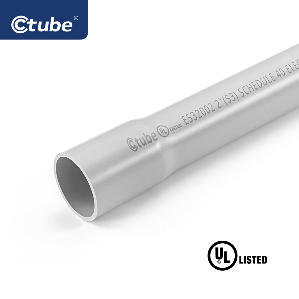
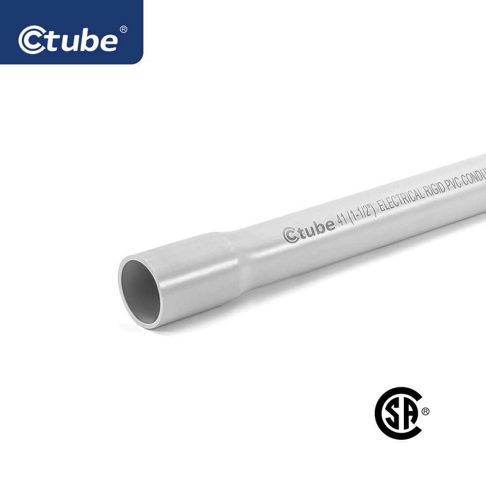
Rigid PVC Conduit (RPVC) – A durable, thick-walled conduit designed for underground and exposed applications. It is resistant to impact and moisture and is commonly used in direct burial and wet locations.
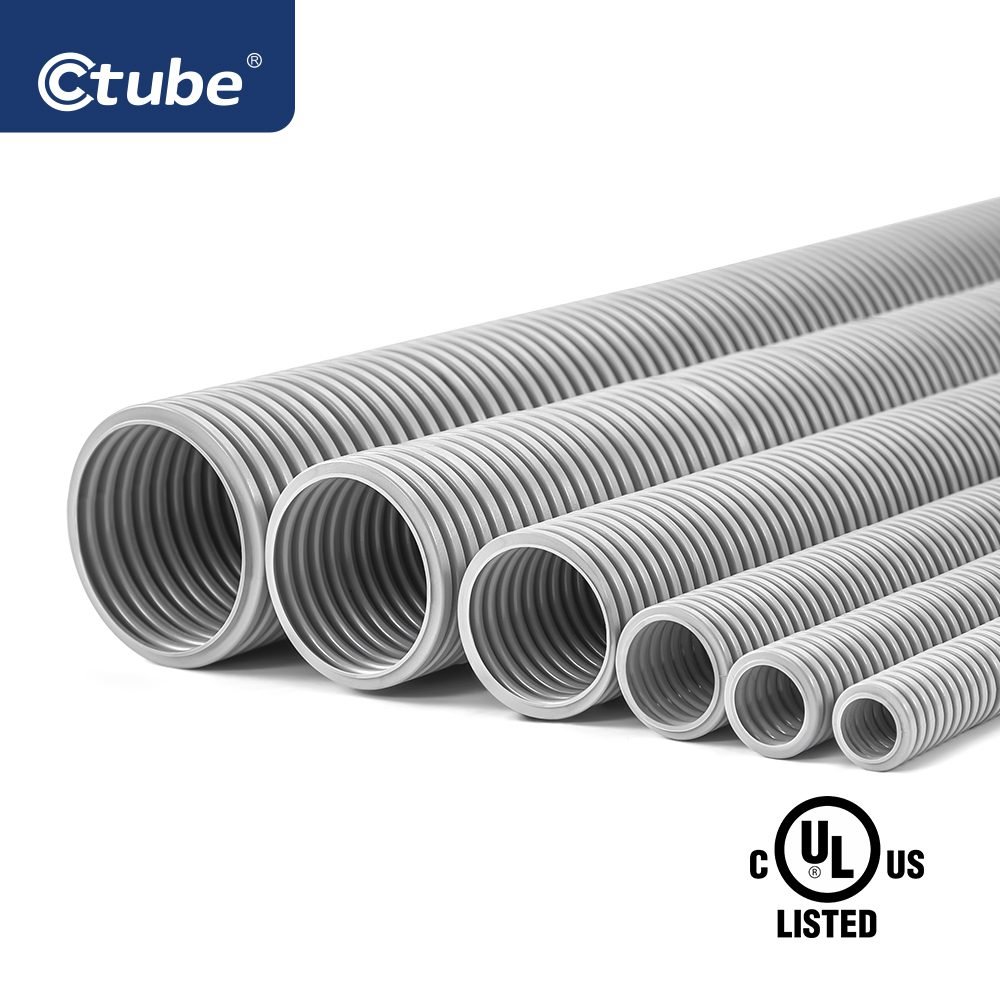
Electrical Non-metallic Tubing (ENT) – A flexible, corrugated PVC conduit that is lightweight and easy to bend. It is mainly used in indoor applications where quick and simple installation is required.
Solar UPVC Conduit – A UV-resistant, weatherproof conduit specifically designed for solar panel installations. It protects wiring from prolonged sun exposure, extreme temperatures, and harsh outdoor conditions, ensuring long-term performance in renewable energy systems.
LSZH (Low Smoke Zero Halogen) PVC Conduit – A specially formulated conduit designed for enclosed environments like tunnels, commercial buildings, and public transport systems. It minimizes toxic smoke and halogen emissions in case of fire, reducing health risks and equipment damage.
5.2.2 Advantages and Disadvantages of PVC Conduit
Advantages:
Corrosion and Chemical Resistance – Unlike metal conduit, PVC does not rust or corrode, making it ideal for humid and corrosive environments.
Lightweight and Easy to Install – PVC is much lighter than metal conduit, reducing labor and transportation costs. It can be easily cut and assembled using solvent cement.
Electrical Insulation – Since PVC is non-conductive, it does not require grounding, simplifying installation.
Weather and UV Resistance – Certain types of PVC conduit are UV-resistant, making them suitable for outdoor applications.
Cost-Effective – Generally more affordable than metal conduits, making it a budget-friendly option for various electrical installations.
Disadvantages:
Lower Mechanical Strength – PVC is not as impact-resistant as metal conduit, making it less suitable for areas with high mechanical stress.
Limited High-Temperature Resistance – PVC can warp or degrade under extreme heat, restricting its use in high-temperature environments.
Expansion and Contraction – PVC expands and contracts with temperature changes, requiring expansion joints in certain installations.
5.2.3 Common Applications of PVC Conduits
Residential Wiring – Used in homes for protecting electrical cables in walls, ceilings, and floors.
Commercial Installations – Ideal for office buildings, retail spaces, and warehouses where non-metallic protection is preferred.
Underground Systems – Frequently used for buried electrical lines due to its moisture resistance.
Wet and Corrosive Environments – Suitable for industrial settings exposed to chemicals or high humidity.
Renewable Energy Projects – Applied in solar and wind energy installations for efficient and long-lasting wiring protection.
6. Schlussfolgerung
Choosing between metal and PVC electrical conduits is not simply about determining which material is better—it depends on multiple factors, including compliance with industry standards, project-specific requirements, budget constraints, and environmental conditions. Each type of conduit has its advantages and ideal applications.
We hope this article has provided valuable insights to help you make an informed decision when selecting electrical conduit solutions for your needs.
Um C-Tube
Ctube is a leading manufacturer with over ten years of experience in the PVC cable ducting industry. We specialize in providing high-quality electrical conduit solutions, ensuring durability, safety, and compliance with international standards. Our AS/NZS 2053 standard conduits and Low Smoke Zero Halogen (LSZH) series wiring ducts meet IEC standards, hold necessary certifications, and have been rigorously tested by third-party laboratories.
If you are interested in learning more about our products or need guidance on choosing the right conduit, feel free to contact us. Thank you for reading!